


Debug Steps for Fisher Valve Positioner DVC6200
- Date:2023-06-20
- Source:本站
- Popularity:1757
#Fisher #DVC6200 #Valve Positioner #Positioner #DVC2000 #DVC6205 #Debug #TREX

As is well known, the Fisher Positioner DVC6200 is a valve mounted digital valve controller under Emerson, which can intelligently control the entire valve assembly. Control your process through important real-time information that can be accessed from any location in the circuit. It can also detect problems before they occur, helping you reduce maintenance time and costs, and improve the operational performance of the facility. This flexible instrument is suitable for various applications equipped with any host and valve, greatly reducing inventory and simplifying personnel training. But the Fisher locator DVC6200 needs to be debugged before use, what are the specific debugging steps? So today, let the technical editor of Hongli Instrument introduce the debugging steps of Fisher Positioner DVC6200, hoping to be helpful to everyone.
Step 1: Connect the Rosemount 475 manual operator
1. Enter the interface and select HART;
2. Enter after selecting online;
3. If there is an alarm signal, select YES and enter;
4. Select 'configure' from the online dropdown menu and press' enter ';
5. Select the calibration menu and press enter;
6. Select auto calibration;
7. Select out of service from the warning menu;
8. After selecting 'Continuue', enter and select 'travel control';
9. Automatic valve calibration does not require operation, just wait until the interface shown in the figure below;
10. Confirm with the OK button after automatic verification is completed;
11. Select OK;
12. Modify to in service status and complete the calibration.
Step 2: DVC Positioner Feedback Debugging Instructions
1. Select manual setup from the configure menu;
2. Select mode protection to change in service to OUT of service;
3. Select to change the instrument mode;
4. Select out of service. Return after entering;
5. Warm reminder to select OK;
6. Select outputs in the manual setup to set the locator feedback;
7. Select output terminal;
8. Select output terminal;
9. Select enable and enter;
10. Be sure to select send and complete the feedback usage settings. Remember to change the valve back to the in service state.
Step 3: Activate the locator calibration button
1. Activate the function under the manual setup menu;
2. Activate the function and select send to complete the setting of the junction box self travel calibration button;
3. Press the debugging button for 3-10 seconds, and the valve will automatically perform stroke verification. The valve will automatically perform stroke verification.
Step 4: Adjustment of sensitivity
If it is found that the valve under the Fisher valve positioner has oscillations or the valve action is too slow, it can be improved by adjusting the Tuning Set (simply understood as sensitivity) and clicking send. There are options for "C D E F G H I J K L M", with valve C reacting the slowest and valve M reacting the fastest. The faster the reaction, the more likely it is to cause vibration.
Step 5: Setting the Instrument Mode
When performing locator verification and parameter adjustment, it is generally necessary to set the Instrument Mode to the Out Of Service (or Not In Service) state. After verification and adjustment, it must be put into In Service!
The above introduces the debugging steps of the Fisher locator DVC6200. If you need to debug the locator later on, you can follow the above steps to avoid errors and obtain accurate and accurate data.
#Fisher #DVC6200 #Valve Positioner #Positioner #DVC2000 #DVC6205 #Debug
- 2026-03-09Announcement of Staff Change-Ellie
- 2025-02-19Flowserve's 2025 price adjustment notice
- 2024-03-27E+H will adjust prices on April 1st.
- 2024-01-242024 Spring Festival Holiday Notice
- 2025-01-202025 Chinese New Year Holiday Notice
- 2023-08-16Fisher Price Adjustment Notice
- 2023-09-12In the new fiscal year,Fisher Price Increase 5.9%
- 2023-06-20Debug Steps for Fisher Valve Positioner DVC6200
- 2023-06-02Knowledge Sharing! Analysis and Solution of 8 Major Types of Pressure Transmitter Faults
- 2023-05-30For Rosemount 3051S transmitter,How to connect the signal line and ground?
- 2023-05-17LinkedIn Account Opened!!!
- 2023-04-27USA Fairchild Industrial Products Company
- 2023-04-27FAIRCHLD Control Valve Maintenance Philosophy
- 2023-04-2351 Holiday Notice
- 2023-04-23Sick Price Adjust
- 2023-04-23Emerson Rosemount February 2023 Price Adjustment
-
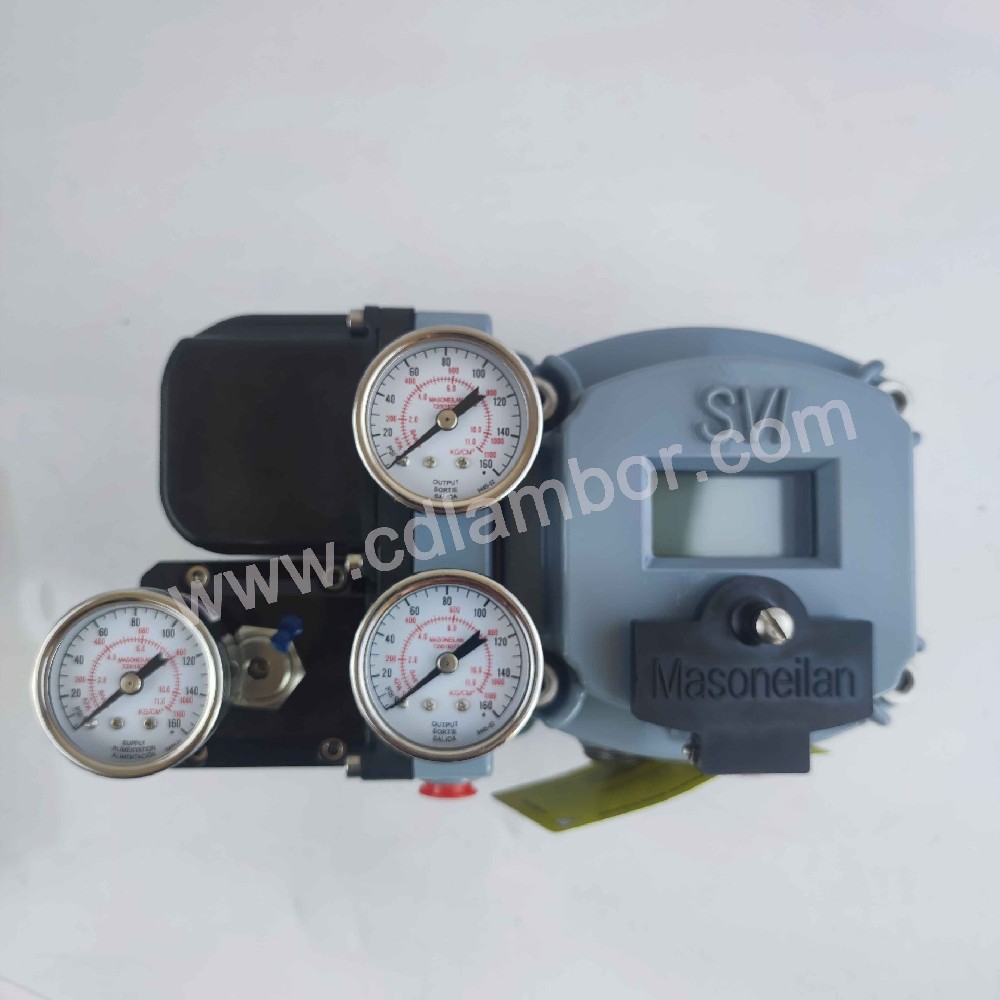 Masoneilan SVI2-22113111 pneumatic control Digital valve positioner
1.DescriptionHow to order
Masoneilan SVI2-22113111 pneumatic control Digital valve positioner
1.DescriptionHow to order -
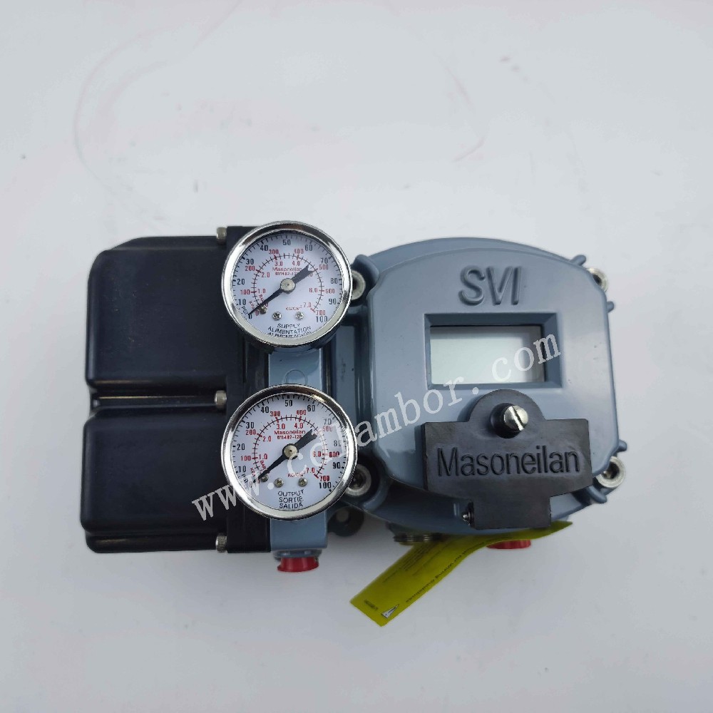 Masoneilan SVI2-31123111 AD diagnostic Level pneumatic control Digital valve positioner
1.DescriptionThe SVI II AP provides for reli...
Masoneilan SVI2-31123111 AD diagnostic Level pneumatic control Digital valve positioner
1.DescriptionThe SVI II AP provides for reli... -
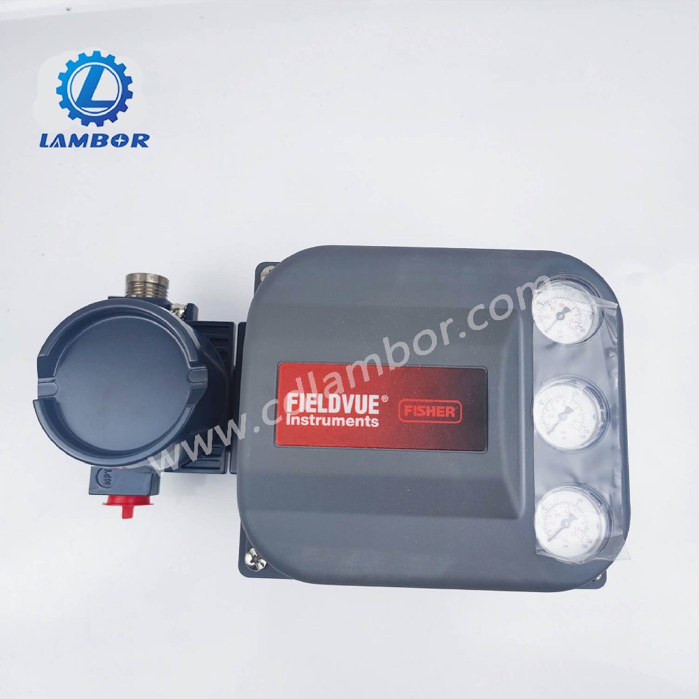 Fisher DVC6200 Hart communication smart digital valve positioner DVC6200F/DVC6200 SIS/DVC2000
DescreptionDVC6200 digital valve controller ...
Fisher DVC6200 Hart communication smart digital valve positioner DVC6200F/DVC6200 SIS/DVC2000
DescreptionDVC6200 digital valve controller ... -
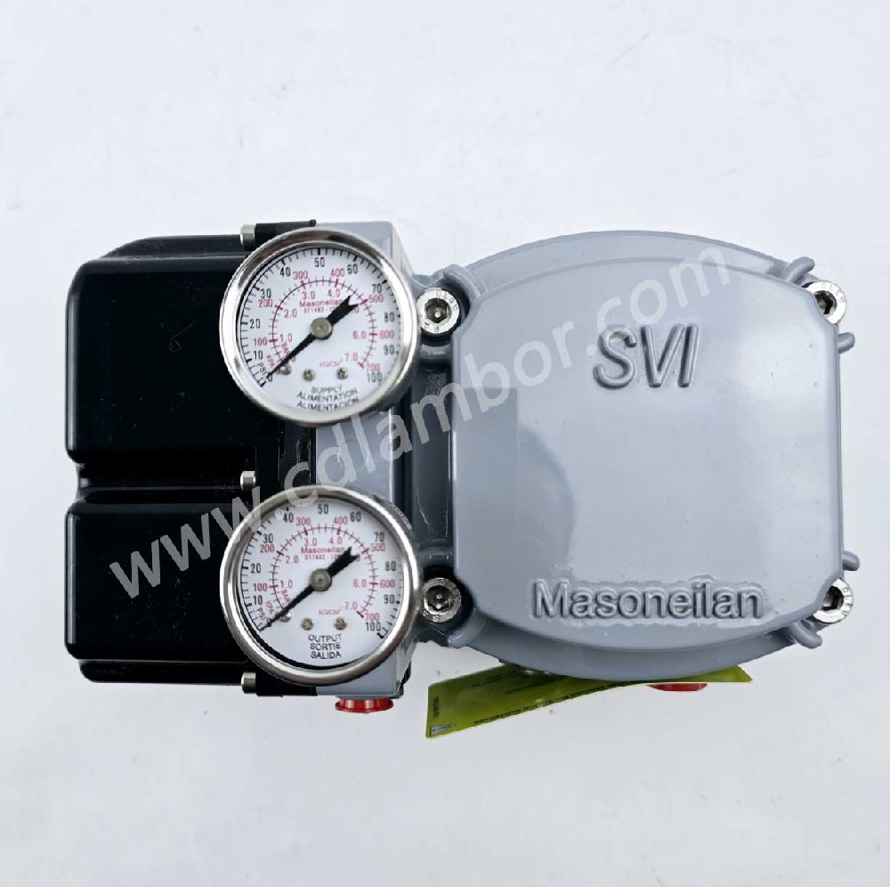 Masoneilan SVI™ FF SVI-2111F124 Valve Positioner FOUNDATION™ fieldbus communication protocol
Masoneilan SVI™ FF Valve PositionerMasoneil...
Masoneilan SVI™ FF SVI-2111F124 Valve Positioner FOUNDATION™ fieldbus communication protocol
Masoneilan SVI™ FF Valve PositionerMasoneil...