


Knowledge Sharing! Analysis and Solution of 8 Major Types of Pressure Transmitter Faults
- Date:2023-06-02
- Source:本站
- Popularity:1758
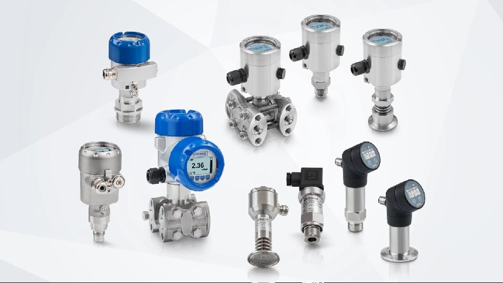
There are many issues with incorrect process parameters reflected by pressure and differential pressure transmitters during on-site installation, such as blockage of pressure pipes, non-standard installation of throttling devices, condensate tanks, and pressure pipes, electromagnetic interference, and maintenance issues. Below is an analysis of some main problems and reasons encountered in the use of pressure transmitters!
A. Transmitter has no output
Inspection and Testing:
1. Check if the transmitter power supply is reversed;
2. Measure whether the power supply of the transmitter has a 24V DC voltage;
3. If it is equipped with a meter head, check if the meter head is damaged (you can short circuit the two wires of the meter head first. If the short circuit is normal, it indicates that the meter head is damaged);
4. Connect the ammeter in series to the 24V power circuit and check if the current is normal;
5. Is the power supply connected to the transmitter power input terminal;
Solution:
1. Connect the power polarity correctly.
2. It is necessary to ensure that the power supply voltage to the transmitter is ≥ 12V (i.e., the input voltage of the transmitter power supply is ≥ 12V).
3. If there is no power supply, check if the circuit is disconnected and if the detection instrument is selected incorrectly (input impedance should be ≤ 250 Ω);
4. If the meter head is damaged, it needs to be replaced. If it is normal, it indicates that the transmitter is normal. At this time, it is necessary to check whether other instruments in the circuit are normal.
5. Connect the power cord to the power terminal.
B. Transmitter output ≥ 20mA
Inspection and Testing:
1. Is the transmitter power supply normal
2. Does the actual pressure exceed the selected range of the pressure transmitter;
3. Is the pressure sensor damaged? Severe overload can sometimes damage the isolation diaphragm.
4. Whether the wiring is loose;
5. Is the power cord wiring correct
Solution:
1. If the transmitter power supply is less than 12VDC, it should be checked whether there is a large load in the circuit. The input impedance of the transmitter load should meet RL ≤ (transmitter power supply voltage -12V)/(0.02A) Ω
2. Select a pressure transmitter with an appropriate range again.
3. If the pressure sensor is damaged, it needs to be sent back to the manufacturer for repair.
4. Connect the wires and tighten them.
5. The power cord should be connected to the corresponding terminal.
C. Transmitter output ≤ 4mA
Inspection and Testing:
1. Is the transmitter power supply normal
2. Does the actual pressure exceed the selected range of the pressure transmitter;
3. Is the pressure sensor damaged? Severe overload can sometimes damage the isolation diaphragm.
Solution:
1. If the transmitter power supply is less than 12VDC, it should be checked whether there is a large load in the circuit. The input impedance of the transmitter load should meet RL ≤ (transmitter power supply voltage -12V)/(0.02A) Ω.
2. Select a pressure transmitter with an appropriate range again.
3. If the pressure sensor is damaged, it needs to be sent back to the manufacturer for repair.
D. Incorrect pressure indication
Inspection and Testing:
1. Is the transmitter power supply normal
2. Is the reference pressure value always correct
3. Is the range of the pressure indicating instrument consistent with the range of the pressure transmitter
4. Is the input and corresponding wiring of the pressure indicating instrument correct
5. The input impedance of the transmitter load should comply with RL ≤ (transmitter supply voltage -12V)/(0.02A) Ω
6. Check if the input terminal of the multi point paper recorder is open when there is no recording;
7. Whether the corresponding equipment casing is grounded
8. Is it wired separately from AC and other power sources
9. Is the pressure sensor damaged? Severe overload can sometimes damage the isolation diaphragm.
10. Whether there are sand, impurities, etc. blocking the pipeline, which can affect the measurement accuracy;
11. Is the temperature of the pipeline too high? The operating temperature of the pressure sensor is -25~85 ℃, but in actual use, it is best to be within -20~70 ℃.
Solution:
1. If the transmitter power supply is less than 12VDC, it should be checked whether there is a large load in the circuit. The input impedance of the transmitter load should meet RL ≤ (transmitter power supply voltage -12V)/(0.02A) Ω.
2. If the accuracy of the reference pressure gauge is low, it is necessary to replace it with a higher accuracy pressure gauge.
3. The range of the pressure indicating instrument must be consistent with the range of the pressure transmitter.
4. If the input of the pressure indicating instrument is 4-20mA, the output signal of the transmitter can be directly connected; If the input of the pressure indicating instrument is 1-5V, a resistor with an accuracy of one thousandth or more and a resistance value of 250 Ω must be connected to the input end of the pressure indicating instrument, and then connected to the input of the transmitter.
5. The input impedance of the transmitter load should comply with RL ≤. If it does not comply, corresponding measures can be taken according to its different characteristics, such as increasing the power supply voltage (but must be below 36VDC), reducing the load, etc.
6. If the input terminal of the multi point paper recorder is open when there is no recording, it cannot carry other loads; 2. Use another recorder with an input impedance ≤ 250 Ω when there is no record.
7. The corresponding equipment casing is grounded.
8. Separate wiring from AC and other power sources.
9. If the pressure sensor is damaged, it needs to be sent back to the manufacturer for repair.
10. When there is sand or impurities blocking the pipeline, it is necessary to clean the impurities and add a filter screen in front of the pressure interface.
11. If the temperature of the pipeline is too high, add a buffer tube to dissipate heat. It is best to add some cold water inside the buffer tube before use to prevent overheating steam from directly impacting the sensor, thereby damaging the sensor or reducing its service life.
In addition to the above faults, pressure transmitters are also prone to the following faults:
E. Installation issues
In steam flow measurement, steam mainly involves two types, one is external supply steam and the other is superheated steam from the boiler. External steam supply is steam that has undergone temperature reduction and pressure reduction, with a low temperature and a large amount of water added. It is not needed when needed, and the steam flow rate is constantly changed according to user requirements. In the actual flow measurement process, sometimes the flow rate is too high and sometimes the flow rate is too low, which is very unstable. It is often necessary to perform blowdown, and the measurement of the transmitter is accurate after each blowdown. However, the frequent blowdown of the steam pipeline can easily lead to steam leakage at various contacts on the pressure pipe.
In the use of measuring superheated steam, the biggest problem was found to be that sometimes the machine was shut down, and after restarting, the flow rate would deviate, leading to misalignment, and sometimes there was still a slight flow display after stopping. Generally, the installation position of the transmitter is lower than the measurement pipeline. However, in actual installation, the condensate tank and transmitter for external steam flow are both higher than the measurement pipeline, and the downward pressure pipeline laid at least 1 meter from the throttling device is also too short.
There is also a problem of inconsistent height between the condensation tank and the measurement pipeline in the superheated steam flow rate of the boiler, resulting in an imbalance in the height of the condensation water and causing a static pressure difference.
F. Blockage of the pressure pipe
In pressure measurement, sometimes the indicated pressure does not change with the operating conditions. After opening the sewage valve, only a small amount of sewage will flow out, which is because there will be a small amount of floating dust in the water quality or compressed air, which will enter the pressure pipe and settle with the water flow. Over time, during operation, the wall of the pressure pipe will corrode and accumulate scale, resulting in blockage.
G. Fault problem with the transmitter equipment itself
In the measurement of lubricating oil pressure, the lubricating oil pressure signal is involved in shutdown interlocking control. The signal measured by the lubricating oil pressure transmitter is transmitted to the computer for display and program comparison. When the pressure is below 0.06MPa, a shortage of oil shutdown signal is issued to shut down the machine.
From the trend chart of the lubricating oil pressure signal, it can be seen that the pressure drops instantaneously and causes the machine to trip. After inspecting the transmitter, it was found that the internal module of the transmitter was damaged. Although the transmitter is regularly calibrated every year, it is used for production after passing the calibration. Due to several years of operation, the accuracy, sensitivity, stability and other performance indicators of the transmitter will gradually decrease, and the internal membranes and integrated blocks will also be damaged and malfunctioned.
H. There are interference issues
In the measurement of the exhaust pressure of an air compressor, the fluctuation of the exhaust pressure signal is significant. After verifying the transmitter, it meets the accuracy requirements and eliminates the fault of the transmitter itself; Check that the pressure conduit and connectors are not damaged or leaking, and the connection of the signal cable is in good contact. However, the cable is led into the control room through the cable tray beside the high configuration room. There is a large amount of electromagnetic interference around.
- 2026-03-09Announcement of Staff Change-Ellie
- 2025-02-19Flowserve's 2025 price adjustment notice
- 2024-03-27E+H will adjust prices on April 1st.
- 2024-01-242024 Spring Festival Holiday Notice
- 2025-01-202025 Chinese New Year Holiday Notice
- 2023-08-16Fisher Price Adjustment Notice
- 2023-09-12In the new fiscal year,Fisher Price Increase 5.9%
- 2023-06-20Debug Steps for Fisher Valve Positioner DVC6200
- 2023-06-02Knowledge Sharing! Analysis and Solution of 8 Major Types of Pressure Transmitter Faults
- 2023-05-30For Rosemount 3051S transmitter,How to connect the signal line and ground?
- 2023-05-17LinkedIn Account Opened!!!
- 2023-04-27USA Fairchild Industrial Products Company
- 2023-04-27FAIRCHLD Control Valve Maintenance Philosophy
- 2023-04-2351 Holiday Notice
- 2023-04-23Sick Price Adjust
- 2023-04-23Emerson Rosemount February 2023 Price Adjustment
-
 Masoneilan SVI2-22113111 pneumatic control Digital valve positioner
1.DescriptionHow to order
Masoneilan SVI2-22113111 pneumatic control Digital valve positioner
1.DescriptionHow to order -
 Masoneilan SVI2-31123111 AD diagnostic Level pneumatic control Digital valve positioner
1.DescriptionThe SVI II AP provides for reli...
Masoneilan SVI2-31123111 AD diagnostic Level pneumatic control Digital valve positioner
1.DescriptionThe SVI II AP provides for reli... -
 Fisher DVC6200 Hart communication smart digital valve positioner DVC6200F/DVC6200 SIS/DVC2000
DescreptionDVC6200 digital valve controller ...
Fisher DVC6200 Hart communication smart digital valve positioner DVC6200F/DVC6200 SIS/DVC2000
DescreptionDVC6200 digital valve controller ... -
 Masoneilan SVI™ FF SVI-2111F124 Valve Positioner FOUNDATION™ fieldbus communication protocol
Masoneilan SVI™ FF Valve PositionerMasoneil...
Masoneilan SVI™ FF SVI-2111F124 Valve Positioner FOUNDATION™ fieldbus communication protocol
Masoneilan SVI™ FF Valve PositionerMasoneil...